Sequence Diagram: Your Guide to Visualizing System Interactions
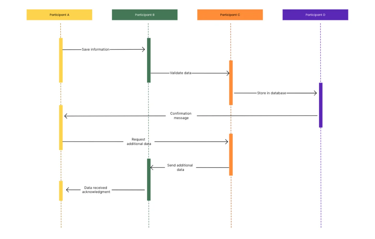
A sequence diagram is an effective UML modeling tool that shows how processes interact with one another and in what order, making complicated system interactions easier to grasp. This template offers a systematic framework for documenting message exchanges between components, allowing developers and stakeholders to view the sequential flow of actions within a system. Whether you're creating new software architecture or documenting current system operations, this template makes communication easier and ensures that everyone knows how components interact over time.
Why Use a Sequence Diagram?
Clarify Complex System Interactions
Sequence diagrams convert abstract system behaviors into explicit visual representations of component interactions. Mapping the actual sequence of message exchanges allows you to detect potential bottlenecks, redundancies, or missing interactions that might otherwise be concealed in text-based documentation. This visual clarity allows teams to immediately comprehend how different pieces of a system communicate and work together.
Improve Development Documentation
Well-designed sequence diagrams are critical development documents that help technical and non-technical stakeholders communicate. This template allows you to generate uniform, professional diagrams that clearly demonstrate system architecture and process flows, making it easier to onboard new team members, manage legacy systems, and ensure that everyone understands how the system works.
Facilitate Better System Design Decisions
Sequence diagrams, which visualize message exchanges and their timing amongst system components, assist teams in identifying optimization possibilities and potential design problems early in the development process. This template provides the framework for modeling alternative interaction patterns, comparing various techniques, and making educated design decisions that improve overall system performance and maintainability.