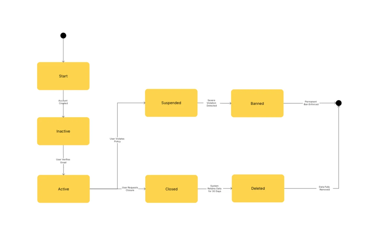
Free State Diagram Template for UML Behavior Modeling (2026)
Free UML state diagram template for 2026. Model object lifecycles, transitions, and events in minutes. Editable online with AFFiNE, no signup.
A state diagram (formally a state machine diagram in UML 2.5) is a behavioral diagram that models the lifecycle of a single object, system, or process — the states it can be in, the transitions between them, and the events and guard conditions that trigger those transitions. Where an activity diagram models how work flows, a state diagram models how one thing changes over time. This free template, built in AFFiNE's edgeless whiteboard, ships with the standard UML 2.5 state machine notation in an editable canvas — no signup, no export limits.
Last updated June 2026 · Compatible with UML 2.5 specification · Built on open-source AFFiNE (50K+ GitHub stars)
Reach for a state diagram when you are:
Skip it when behavior doesn't have distinct named states (use an activity diagram for general workflows) or when you need cross-object interaction modeling (use a sequence diagram).
This template ships with the seven core elements of the UML 2.5 state machine notation:
| Element | Symbol | Purpose |
|---|---|---|
| Initial state | Filled black circle | The starting state of the modeled entity |
| State | Rounded rectangle with name | A distinct condition the entity can be in |
| Transition | Arrow labeled event [guard] / action | Movement from one state to another |
| Choice / decision | Diamond | Branch on a guard condition mid-transition |
| Self-transition | Loop arrow back to same state | An event handled without leaving the state |
| Composite state | Rounded rect containing nested states | A state with internal sub-states |
| Final state | Bullseye (filled circle inside open circle) | The terminal state — no further transitions |
The Object Management Group's UML 2.5 specification is the canonical source for notation rules; this template follows that spec.
"A state machine is used to specify discrete behavior of a part of a designed system through finite state transitions." — OMG Unified Modeling Language Specification, v2.5.1
On the transition syntax used in this template, the same spec states:
"A Transition represents an arc between exactly one source Vertex and exactly one Target Vertex. It may form part of a compound transition, which takes the StateMachine from one steady state configuration to another." — OMG Unified Modeling Language Specification, v2.5.1
Most teams produce a useful first-pass state diagram in 20-40 minutes once the modeled entity and its lifecycle scope are agreed on. Follow these five steps:
Name the entity being modeled. A state diagram models one thing: an order, a user session, a connection, a document. If you find yourself adding states that belong to a different entity, you've blurred the model — split it into two diagrams.
List every state the entity can be in. Walk through the entity's life from creation to deletion and write each distinct state. Aim for 5-12 states; if you cross 15, group related states into composite states. IBM's requirements modeling guidance treats this ceiling as a readability threshold.
Connect states with transitions and label them with events. Draw an arrow from source state to target state for every legal change. Label each transition with the triggering event, an optional guard condition in square brackets, and an optional action after a slash (for example, submit [valid] / sendEmail).
Add guard conditions and self-transitions. When the same event can lead to different states depending on context, attach a guard to each branch. When an event is handled without changing state (a counter increment, a log entry), draw a self-transition loop. Both are common sources of forgotten edge cases.
Group related states into composite states when the model grows. Wrap a cluster of sub-states inside a composite state when they share entry/exit transitions. Composite states reduce arrow tangle and make the high-level lifecycle scannable at a glance.
After step 5, switch to AFFiNE's page mode to capture each state's invariants, entry/exit actions, and test cases alongside the diagram in one document — page and edgeless live in the same file.
| Diagram type | Best for | When to choose this instead |
|---|---|---|
| State diagram | An entity's lifecycle, states, and transitions | You're modeling one thing changing over time |
| Activity diagram | Workflow with decisions and parallelism | The process spans multiple actors or systems |
| Use case diagram | Functional scope and actors | You need to align stakeholders on what the system does |
| Sequence diagram | Time-ordered messages between objects | You need message-level detail across multiple objects |
| Communication diagram | Object collaborations and structural links | You care about interaction structure, not state lifecycle |
| Class diagram | Static structure of classes and attributes | You're designing the data model |
For end-to-end coverage of the UML 2.5 family, browse the full diagram template library. For event-driven message modeling that pairs naturally with state machines, see the UML sequence diagram guide.
A UML state diagram (formally a state machine diagram in UML 2.5) is a behavioral diagram that models the lifecycle of a single entity as a finite set of states, the transitions between them, and the events and guard conditions that trigger those transitions. It is the standard UML diagram for modeling stateful behavior in software, protocols, and business processes.
An activity diagram models the flow of work across actions and decisions — the verbs of a process. A state diagram models the lifecycle of one entity — the nouns and how they change. Use an activity diagram for "submit invoice → approve → pay"; use a state diagram for "draft → submitted → approved → paid → archived".
The seven core elements are initial state, state (a named condition), transition (an arrow labeled event [guard] / action), choice (diamond for mid-transition branching), self-transition (loop arrow), composite state (a state containing nested states), and final state. These appear in this template as a ready-to-customize palette.
Yes — this template is free, requires no signup, and runs entirely in the browser via AFFiNE. You can edit, duplicate, export, or self-host the underlying open-source AFFiNE editor. No watermark, no upgrade prompt.
Use composite states the moment your diagram has more than ~10 flat states or when several states share the same entry/exit transitions. Composite states let you nest sub-states inside a parent, dramatically reducing transition tangle and exposing the high-level lifecycle while preserving detail.
Industry-standard UML guidance suggests 5-12 states per diagram as a working comfort zone, with 15 as a readability ceiling. Beyond that, decompose using composite states or split the model by lifecycle phase. The same ceiling appears in IBM's published requirements-modeling guidance.
This template and accompanying guidance reflect the OMG UML 2.5.1 specification, IBM's published requirements-modeling guidance, and conventions widely adopted across enterprise software-engineering practice. Notation was reviewed against the ISO/IEC 19505 UML standard. Best-practice ceilings (5-12 states per diagram, composite states for nesting) and time-investment figures reflect commonly cited industry guidance; verify against your team's internal standards before adopting them as hard rules.