Free Use Case Diagram Template for UML System Design (2026)
Free UML use case diagram template for 2026. Map actors, system boundaries, and interactions in minutes. Editable online with AFFiNE, no signup.
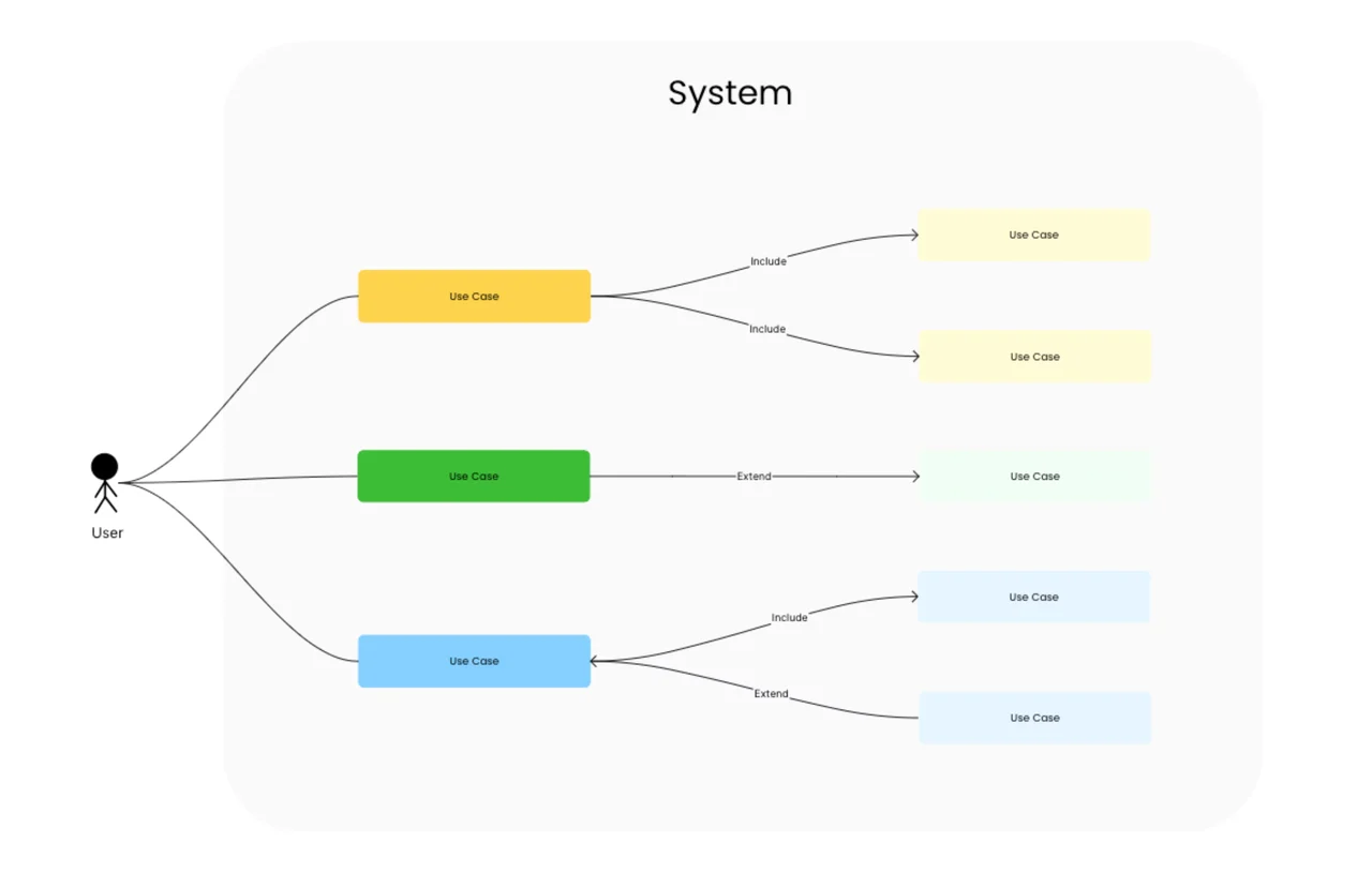
A use case diagram is a UML behavioral diagram that visualizes the functional requirements of a system by mapping interactions between actors (users or external systems) and use cases (discrete units of system behavior) inside a defined system boundary. It answers the question "what should this system do, and for whom?" — without prescribing how the system does it. This free template, built in AFFiNE's edgeless whiteboard, gives you the standard UML 2.5 notation in an editable canvas — no signup, no export limits.
Last updated June 2026 · Compatible with UML 2.5 specification · Built on open-source AFFiNE (50K+ GitHub stars)
Reach for a use case diagram when you are:
Skip it when interactions are purely time-sequenced (use a sequence diagram template instead) or when you need to model class structure (use the UML class diagram template).
This template ships with the five core elements of the UML 2.5 use case notation:
| Element | Symbol | Purpose |
|---|---|---|
| Actor | Stick figure | A user role or external system that interacts with the modeled system |
| Use case | Ellipse | A discrete unit of system behavior that delivers value to an actor |
| System boundary | Rectangle | Defines what is inside vs. outside the system being modeled |
| Association | Solid line | Connects an actor to the use cases they participate in |
| «include» / «extend» | Dashed arrow | Use case relationships for reuse and conditional behavior |
The Object Management Group's UML 2.5 specification is the canonical source for notation rules; this template follows that spec.
"A use case is the specification of a set of actions performed by a system, which yields an observable result that is, typically, of value for one or more actors or other stakeholders of the system." — OMG Unified Modeling Language Specification, v2.5.1
On the actor side, the same spec states:
"An Actor specifies a role played by a user or any other system that interacts with the subject." — OMG Unified Modeling Language Specification, v2.5.1
Most teams produce a useful first-pass use case diagram in 15-30 minutes once the actors and primary use cases are identified. Follow these five steps:
Identify the actors. List every user role and external system that will interact with your system. Group by primary actors (those who initiate use cases) and secondary actors (those who support them). IBM's requirements modeling guidance recommends 5-9 primary actors as a working ceiling per diagram.
Draw the system boundary. Place a labeled rectangle at the center of the canvas — every use case lives inside it; every actor lives outside it. The boundary is the contract between system and environment.
List the use cases. For each primary actor, ask "what discrete outcomes do they need from this system?" Each answer becomes a use case ellipse inside the boundary. Aim for verb-noun phrasing ("Submit invoice", "Review proposal") and 10-20 use cases per diagram.
Connect actors to use cases with associations. Draw solid lines from each actor to every use case they participate in. If a line crosses three or more other lines, the layout needs work — drag the actor closer to its use cases.
Add «include» and «extend» relationships last. Use «include» for behavior that is always part of another use case (for example, "Validate session" included in "Submit invoice"). Use «extend» for optional behavior (for example, "Apply discount" extends "Submit invoice"). Keep these to a minimum — overuse turns the diagram into a maintenance burden.
After step 5, switch to AFFiNE's page mode to add stakeholder notes alongside the diagram in one document — page and edgeless live in the same file.
| Diagram type | Best for | When to choose this instead |
|---|---|---|
| Use case diagram | "What" — functional requirements + actors | You need to scope a system or align stakeholders |
| Activity diagram | "How" — workflow inside a single use case | You need to model a multi-step business process |
| Sequence diagram | Time-ordered interactions between objects | You need message-level detail for one scenario |
| Communication diagram | Object collaborations and links | You care about structure, not message timing |
| Component diagram | Physical components and dependencies | You're designing the deployment-level architecture |
| Class diagram | Static structure — classes, attributes, methods | You need to design the data model |
For end-to-end coverage of the UML 2.5 family, browse the full diagram template library. For data-pipeline modeling that pairs naturally with use cases, see the data flow diagram guide; for time-ordered interaction modeling, see the UML sequence diagram guide.
A use case diagram is a UML behavioral diagram that shows the functional scope of a system as a set of interactions between actors and use cases, bounded by a system rectangle. It is one of 14 official diagram types in UML 2.5 and is the most widely used UML diagram for requirements communication.
The four core elements are actors (user roles or external systems), use cases (units of system behavior, drawn as ellipses), the system boundary (a labeled rectangle containing all use cases), and associations (solid lines connecting actors to use cases). «include» and «extend» relationships are optional additions for behavior reuse.
Use a use case diagram when you need a visual scope contract across many actors and many use cases at once — common in early-stage product scoping, requirements review meetings, and integration audits. Use user stories when you're inside an agile sprint and need a unit-of-work format for the backlog. The two are complementary: one use case typically expands into 3-10 user stories.
Yes — this template is free, requires no signup, and runs entirely in the browser via AFFiNE. You can edit, duplicate, export, or self-host the underlying open-source AFFiNE editor. No watermark, no upgrade prompt.
A use case diagram models who uses the system and what outcomes they need — it is intentionally non-sequential. A flowchart models the order of steps inside a single process. If you need to show "first the user does X, then Y", use a flowchart or an activity diagram. If you need to show "these five actors need these twelve outcomes", use a use case diagram.
Industry-standard UML guidance (per the OMG specification and IBM's requirements-modeling documentation) suggests 5-9 primary actors per diagram as a readability ceiling. Beyond that, split the model into multiple diagrams grouped by subdomain.
This template and accompanying guidance reflect the OMG UML 2.5.1 specification, IBM's published requirements-modeling guidance, and conventions widely adopted across enterprise software-engineering practice. The notation in this template was reviewed against the ISO/IEC 19505 UML standard. Best-practice ceilings (5-9 actors, 10-20 use cases per diagram) and time-investment figures reflect commonly cited industry guidance; verify against your team's internal standards before adopting them as hard rules.